The Battle Creek Special Antenna
There are 2 versions of the Battle Creek Special shown - a wire version. which will work out first. The traps are made of coax cable as described by W1FB. The second version is a 'real' vertical make of tubes complete with a description of the traps... I hope to unsecret the mystery of the Battle Creek Special and the construction of it.
GENERAL
This antenna is designed for 40, 80 and 160 meters to complement a tri-band beam normally taken on DXpeditions for 10, 15 and 20 meters, so six bands can be worked with only two antennas.
CONSTRUCTION
A detailed description of a wire construction of the Battle Creek Special published Jeff Briggs, K1ZM.
The material used is high strength aluminum tubing, 6061-T6 alloy, in sizes ranging from 2 inches to 1 inch (5 to 2.5 cm O.D.). Guy lines are 3/32 inch (2.4 mm) dacron double braided rope with a rating of 260 pounds (118 kg) breaking strength. Wind survival rating is 100 MPH (160 km/h) assuming proper guy rope anchors.
CONFIGURATION
The antenna is a vertical element 48 feet (15 meters) high with traps for 40 and 80 meter operation, with a top loading guy wire connected BELOW the 80 meter trap to resonate the antenna on 80 meters and a top loading wire connected ABOVE the 80 meter trap for 160 meter operation. It is guyed four ways at three levels so the side guy ropes act as a hinge allowing it to be "walked up" by one person.
Original traps were coaxial as in Oct.'81 HAM RADIO, May'81 QST and Dec.'84 QST. These work fine at powers up to 800 watts or so, but run "hot" at "full legal power"!! The latest design uses regular L/C traps with the "L" being #10 wire and the "C" made from lengths of R/G 213U (approx 30pf/ft.) The mechanical construction is a little complicated, but not difficultly (The coax cap. fits inside of the aluminum mast sections. A single approx 3' for 40 and parallel approx 4' sections for 80) The 40 meter trap uses 13 T on 11/2 CPVC.
The Mechanics of Coaxial Traps
DOUG'S DESK BY DOUG DeMAW, W1FB
I am frequently asked, what's the best way to build an antenna trap? Certainly, the art of building these components has been covered In the amateur literature by numerous authors in the past. Early-day homemade traps consistecl of a suitable piece of B & W Miniductor stock and a parallel capacitor that could handle the RF current without overheating or changing value. Suitable capacitors were plentiful in the days when kW amplifiers were the exception rather than the rule. But now that linear amplifiers are plentiful, it becomes a challenge to build an antenna trap that won't overheat or become short-circuited. The outlook improved markedly when R. H. Johns described his coaxial traps in OST magazine. These traps rely upon the inherent capacitance in coaxial cable, along with the inductance that results when the proper number of cable turns are wound on a coil form. Therefore, the number of turns required for a particular resonant frequency is a function of the capacitance per foot of the cable used for the trap.


(Trap drawings courtesy PI4CC)
Other authors have written articles about coaxial traps and their use. A computer program for accurately designing coaxial traps is one of the many contained on the VE3ERP 3.5 inch diskette for DOS, which is available for $5. (Note: download here). There is another nice tool for coax trap design. Tony Field, VE6YP, released a Windows based program producing reliable and proven results. Therefore, I will not include the design procedures for coaxial traps in this article. Instead, let's discuss trap performance and the mechanical aspects of building these devices. Coaxial traps that are wound with RG-58 cable will safely accommodate the full legal amateur power level. They may be made more compact and lightweight by using miniature RG-174 coax and smaller coil forms, but the maximum safe power level is 500 watts for the smaller coax. RG-174 coaxial traps are desirable for portable multiband antennas. Conversely, RG58 cable requires a larger and heavier coil form, which must be a consideration if several traps are contained in one antenna. It becomes obvious that strong, thin-wall coil forms are better for these larger traps. The weight of the coax for 160 and 75 meter traps, especially, is a tad on the hefty side to begin with PVC plumbing pipe is readily available and works nicely as coil-form material. Try to select the thin-wall variety. The traps pictured in this article are wound on thick wall pipe (3/16 inch wall thickness) with a 2 3/8 inch OD, simply because that's what I had on hand. The 1.9 MHz trap weighs 14 ounces without the end caps and eye bolts installed. Fiberglass, or thin-wall cloth phenolic tubing, would reduce the weight substantially. The 3.85 MHz trap weighs 11 ounces with the 3/8 inch Delrin end plugs and other hardware in place. Wooden end plugs, boiled in canning wax, would decrease the weight by a couple of ounces.
Trap Quality
Coaxial traps have a relatively high value of Q. I observed this when using a Kenwood DM-81 dip meter to check the trap resonance. Despite the small dipper coils, a sharp indication was obtained when the dipper probe was 8 inches away from the end of the traps. This indicated high Q (preferred). Owing to this characteristic, the impedance of coaxial traps is high. The effective operating bandwidth of the traps is on par with the 2:1 SWR bandwidth of most dipoles, despite the high Q. The longevity of coaxial traps can be improved if you are lucky enough to find some Tellon-insulated RG-58 cable that has UV-resistant outer insulation. I don't know if cable of this type can be obtained but Teflon coax is available. Some form of UV protection (to prevent degradation of the traps) is desirable. If 2 3/4 inch shrink tubing were available, it would be an ideal covering for the traps. I have had good results with tool-handle dip compound for protecting coaxial traps I built in the past. Two layers of the material were used. The traps held up well during an outdoor test period of five years. Once dried, the compound had no effect on the trap resonance or Q.
Mechanical Details
A 1/2 inch by 2 inch strip of doublesided PC board material is used at each end of the trap. Each strip is held in place by means of two 6-32 flathead screws. The strips serve as conductors between the antenna and the internal junctions of the trap. Lock washers are used at all screw points to ensure long-term electrical integrity. The trap end plugs are optional. I prefer to use them because they deter wasps from building nests inside the tubing, and because they prevent internal build-up of ice or snow. The plugs are fitted with eye bolts to provide anchor points for the antenna wire. If you omit the plugs, you may drill a hole at each end of the trap for use as an antenna-wire anchor point. Two solder lugs are used on each PCboard strip. One is installed outside the trap for the antenna connection. The other one is used as a soldering terminal for the coaxial cable, inside the trap. Each end plug is held in place by three 6-32 screws.
The plastic plugs are drilled and tapped for 6-32 screws (three for each plug). If wooden plugs are used, you may use flathead wood screws to affix them. It is wise to seal the open ends of the trap cable with epoxy cement, GOOP brand sealant, or Coax Seal 9(r) putty. This will prevent moisture from migrating inside the shield braid and contaminating the RG-58 cable.
Electrical Considerations
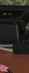
The traps described in this article are wound with RG-58AIU. Other small 50 ohm coaxial cable is suitable. If you want to add a margin of safety for high power, you can use RG-8X coax. The Radio Works, Inc.s catalog lists their top-of-the-line RG-8X as CQ-8X M/M. It is a marine-grade cable that is high-temperature stable and contains solid dielectric crushproof insulation. Since RG-8X has a greater OD than RG-58, a longer coil form would be required. Fig. 2 shows the assembled 160 and 75 meter traps. The medium-size unit with the end plugs is for 3.85 MHz. Included in the photo is a 1 inch OD mini trap for 20 meters that was built by my son, Dave DeMaw, N8HLE, for use in his QRP trap dipole. This tiny trap is wound with RG-174 and weighs one ounce. It is coated with tool-handle dip. Some of you are probably wondering where an amateur might use a 160 meter trap. Traps for that frequency are useful in a 75 meter fullwave loop to permit 1.8 MHz operation. Half frequency loops (e.g., a 75 meter loop on 160 meters) perform miserably. They provide substantially less gain than a full-size dipole. However, if the loop is opened electrically opposite the feed point by means of a 160 meter trap, the antenna performs as a 160 meter " scrunched" dipole and works quite well. The trap effectively opens the loop at 160 meters, but closes it for the bands below 160 meters. Multiband operation assumes that tuned feeders are used with the 75 meter loop. Note that the center conductor at one end of the coil is connected to the shield braid at the opposite end of the coil. The trap turns are close-wound.
75 Meter Trap Constants
The following electrical constants are based on a coil-form diameter of 2.375 inches and RG58A/U cable for the 3.85 MHz trap described here. An effective capacitance (28.5 pF/ft.) of 241 pF and an inductance of 7.14 uH (Xc, XL = 172) results from using the required 104 inch length of coax cable. The coil length is 2.53 inches and the form factor is 0.98:1. There are 12.45 close-wound turns of cable wrapped around the 4 3/4 inch length of PVC tubing. Table I lists winding information for a variety of coaxial traps. The referenced QST article by R. Sommer. N4UU, contains charts that can be used to design traps for any HF band when using various coil form diameters. If you have an IBM-compatible computer, you can utilize the aforementioned VE3ERP software to design these traps precisely. The recommended form factor (diameter to length ratio) for these traps is from 1:1 to 2:1. This range ensures the high Q that makes the traps effective for divorcing the unwanted parts of an antenna.
| MHz |
Form O.D. |
Form L |
Turns No. |
Coax L |
Net C |
Net L |
| 7.15 |
2 3/8 |
4.0 |
11.85 |
66.51 |
152.24 |
3.28 |
| 3.60 |
2 3/8 |
4 1/2 |
13.20 |
110.25 |
255.00 |
4.00 |
Table 1.
The letter L in this table (other than the right-hand column) refers to length, which is given in inches before the shield braid is separated from the inner conductor The braid at one end of the coil must be long enough to reach to the center conductor at the opposite end of the trap. The remaining shield braid and the two center-conductor stubs are approximately 1 inch long Resonance of the completed traps may be checked with a dip meter while monitoring Ihe dipper signal with a calibrated receiver.
Footnotes:
R.H. Jonhns, Coaxial Cable Antenna Traps, QST, May 1981 pp. 15-17
D. DeMaw, Lightweight Trap Antennas, Some Thoughts, QST june 1983 pp-15-18
R. Sommer, Optimizing Coaxial-Cable Traps, QST Dec 1984 pp 37-42
HAMCALC send $5 to Geo Murphy, VE3ERP, 77 Mckenzie St., Orillia, ON L3V 6A6, Canada.
Источник: http://www.ok1rr.com/index.php/antennas/26-the-battle-creek-special-antenna |