| Меню сайта |
|
 |
| Категории раздела |
|
|
| Наш опрос |
|
|
| Статистика |

Онлайн всего: 1 Гостей: 1 Пользователей: 0 |
|
|
One board filter IC-718 W4RT
One board filter IC-718 W4RT
For the ICOM IC-718
W4RT Electronics™ ™
A Division of CyberAir Development Corporation
www.w4rt.com
17 March 2005
The ONE BOARD FILTER (OBF-718) is an accessory for the ICOM IC-718. W4RT Electronics provides the OBF-718 as a high-performance, lower-cost alternative to the ICOM optional filters for the IC-718, and the OBF-718 allows the inclusion of two filters rather than the single one by ICOM. The filters used in the OBF-718 are the famous Collins Mechanical filters. The CW filter has a 500 Hz bandwidth and the SSB filter has a 2300 Hz bandwidth. Proper termination is included on the PCB.
The OBF-718 is available in three forms, viz., OBF-718-DIY (CW and SSB filters), OBF-718-CW-DIY (CW filter only), and OBF-718-SSB-DIY (SSB filter only). The following installation instructions can be used to install all three; however, depending upon which OBF-718 you are installing, you may omit certain steps. For example, if you are installing the OBF-718-CW-DIY, you do not remove the stock MuRata filter. The OBF-718 can not be utilized if any Option filter is already installed unless that filter is removed (which can be done by W4RT Electronics if the installation is being performed by W4RT Electronics).
Please READ the following BEFORE INSTALLING your OBF-718.
Installation is not trivial, so you should be confident that you have the skills and experience needed to do the job correctly. You can damage your IC-718, so be very careful. W4RT Electronics assumes NO responsibility for any damage that may be caused by your installation. Further, W4RT Electronics doesn't provide technical assistance during your installation. If you need help, then have W4RT Electronics perform the installation for the stated fee on www.w4rt.com BEFORE you attempt the install. W4RT Electronics is not a radio repair facility. If you damage your radio, you will have to send it to ICOM or another repair shop.
1. Remove the bottom cover from the IC-718. Retain these screws to replace the bottom cover.
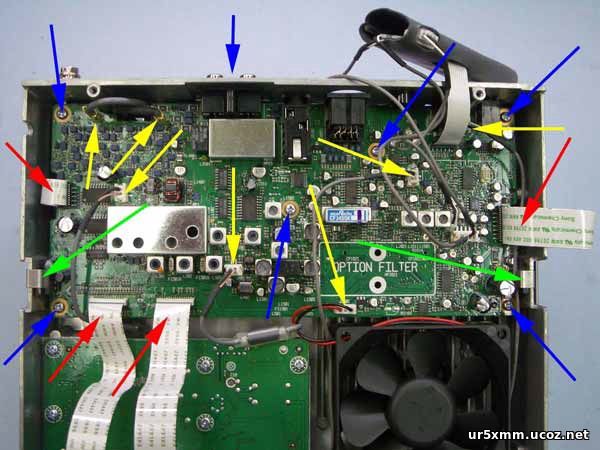
2. Refer to Fig. 1 and also page 50 in the IC-718 manual for reference.
3. Carefully unplug the four (4) ribbon cables (red arrows) from the PCB referred to as the MAIN unit.
4. Carefully unplug the two (2) coax connectors and five (5) plugs (yellow arrows) from the PCB.
5. Carefully remove the two (2) Tr-clampers (green arrows) from IC3401 and IC2901.
6. Remove the seven (7) screws holding the PCB in place (blue arrows). Retain these screws to replace the PCB.
7. Remove the PCB from the IC-718 with care and note that the DSP UT-106 remains attached to the MAIN unit
PCB.
8. Note the location of the MuRata filter (white arrow just above the location on the PCB marked OPTION
FILTER) to be removed ONLY IF the OBF-718-DIY or OBF-718-SSB-DIY is being installed. In this case,
the SSB filter is replacing the MuRata filter. It is NOT removed if you are installing the OBF-718-CW-DIY or
if you are installing the OBF-718-SSB-DIY as the Option filter.
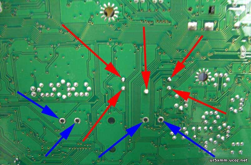
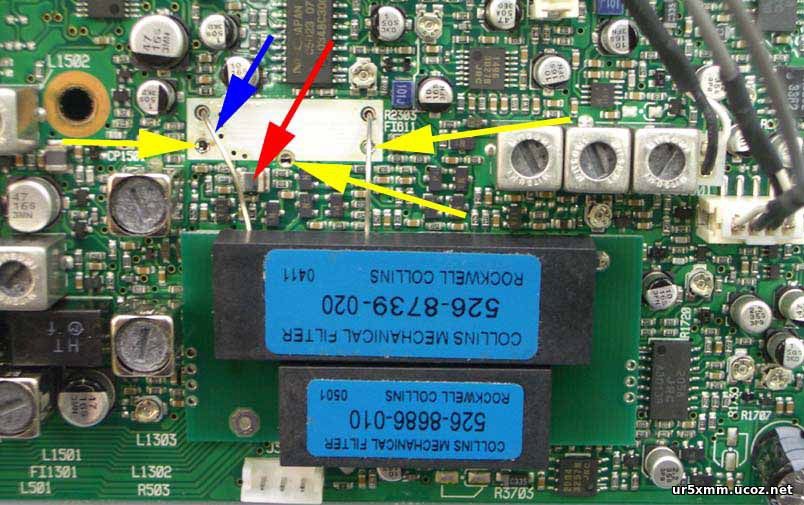
9. If you are to remove the MuRata filter from the PCB, then first CAREFULLY remove the solder from the five
(5) points shown in Fig. 2 by the red arrows.
10. Now, CAREFULLY remove the MuRata filter and place it aside.
11. Locate the OBF-718 to be installed and remove the film from the double-sided tape on the bottom side of the
OBF-718. If you are installing the OBF-718-SSB as the Option filter, cut off the two wires coming from the top
of the OBF-718-SSB PCB (these two wires are used only if you remove the MuRata filter).
12. Notice the four holes denoted by the blue arrows in Fig. 2. These are discussed in Step 13.
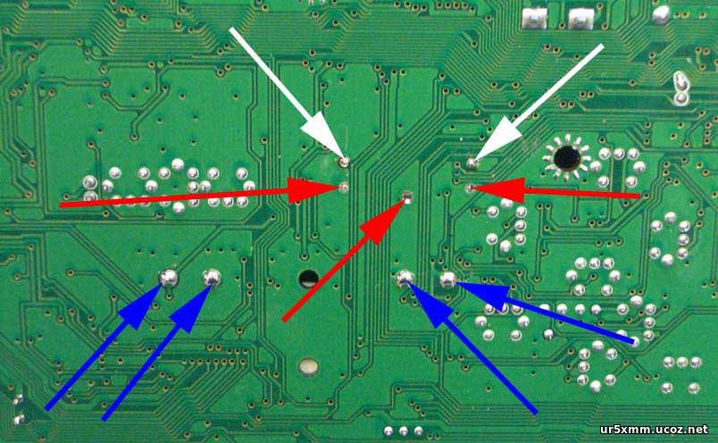
13. CAREFULLY place the four (4) wires from the bottom of the OBF-718 into the four (4) holes (blue arrows) shown in Fig. 2. Also, route the two (2) wires from the top side of the OBF-718 through the holes indicated by the white arrows shown in Fig. 3. It is best to attempt to route all six (6) wires at the same time you place the OBF-718 onto the IC-718 PCB. Do not put wires in the holes denoted by the red arrows in Fig. 3 (same as the yellow arrows in Fig. 4 when viewed from the other side of the PCB). WARNING: Be sure that the wire from the OBF-718 denoted by the blue arrow in Fig. 4 does NOT touch the inductor shown by the red arrow.
14. CAREFULLY solder the six (6) locations denoted by blue and white arrows in Fig. 3. Cut off excess wire length from the OBF-718.
15. Reinstall the IC-718 PCB. Replace screws first, then the plugs, cables and Tr-clampers, and finally the bottom cover.
16. After you have the radio ready to operate, then perform the Initial Set Mode Operation (see page 41 in the IC-718 Manual).
• If you have installed the OBF-718 (both filters), then set OPTION Filter menu selection to FL-52A. The Option filter is now the CW-Narrow selection. The stock MuRata filter has been replaced by the Collins SSB filter and no additional selection is required.
• If you installed the OBF-718-CW, then set OPTION Filter menu selection to FL-52A. The Option filter is now the CW-Narrow selection.
• If you installed the OBF-718-SSB, then set menu selection to FL-65 if you want to use it as the Option filter. If you replaced the MuRata filter with the OBF-718-SSB, then set the menu selection to NO.
NOTE: If you are interested in understanding more about the performance of these filters, then see the QRP Quarterly article by K9QI (http://www.w4rt.com/obf/QQ-Oct-01-Filter-Review.pdf). Although the radio under discussion is the Yaesu FT-817, both the FT-817 and the IC-718 use the MuRata CFJ455K ceramic filter as the stock filter. The performance of the filters in both radios is essentially the same.
WARRANTY: ONE BOARD FILTER is warranted for a period of one (1) year from the date of purchase to be free of electrical defects in materials and workmanship. If the ONE BOARD FILTER is determined to be defective, the defective item(s) will be repaired or replaced, at the sole option of W4RT Electronics, provided that the purchaser returns said item(s), postage prepaid, with proof of purchase to W4RT Electronics, ATTN: Technical Support, 3077-K Leeman Ferry Rd, Huntsville, AL 35801. Include a description of the problem, daytime phone number, email address, and return mailing information. Any modification to the ONE BOARD FILTER by purchaser voids the warranty. The warranty applies only to the original purchaser and is not transferable. Any damage to the ONE BOARD FILTER due to the installation method or technique used by purchaser is the sole responsibility of purchaser and W4RT Electronics has no liability whatsoever.
17 March 2005
Copyright © 2005 by CyberAir Development Corp. All rights reserved.
W4RT Electronics, W4RT, and ONE BOARD FILTER are trademarks of CyberAir Development Corp. |
| Категория: Трансиверы Icom | Добавил: UR5XMM (08.08.2016)
|
| Просмотров: 4575 |
| Рейтинг: 0.0/0 |
| Всего комментариев: 1 | |
|
|
|
|
|
|
| Вход на сайт |
|
|
| Поиск |
|
|

|